MAKE A MEME
View Large Image

| View Original: | BWR Mark I Containment sketch primary.png (826x852) | |||
| Download: | Original | Medium | Small | Thumb |
| Courtesy of: | commons.wikimedia.org | More Like This | ||
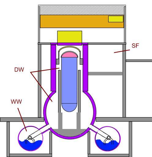
| Keywords: BWR Mark I Containment sketch primary.png en Rough sketch of a typical Boiling water reactor BWR Mark I Concrete Containment with Steel Torus including downcomers as used in the BWR/1 BWR/2 BWR/3 and some BWR/4 model reactors The primary containment is outlined in purple DW Drywell WW Wetwell SF Spent Fuel Pool light blue with pink dome Reactor Pressure Vessel purple Secondary Concrete Shield Wall fr Diagramme/coupe d'un réacteur à eau bouillante REB typique de type Mark I à enceinte de confinement en béton avec tore d'acier sous-jacent tel qu'utilisé dans les réacteurs de type REB/1 REB/2 REB/3 et certains REB/4 es Diagrama/corte esquemático de un reactor de agua en ebullición tipico del tipo Mark I con recinto de contención en hormigón con toro subyacente en acero como los utilizados en los reactores de tipo BWR/1 BWR/2 BWR/3 y algunos BWR/4 ca Esquema d'un reactor d'aigua en ebullició BWR Boiling water reactor de tipus Mark I amb contenció de formigó i torus d'acer incloent baixants com els utilitzats en els models de reactor BWR/1 BWR/2 BWR/3 i alguns BWR/4 DW Pou sec WW Pou moll SF Piscina del combustible gastat Sketched in Paint net using 826 x 852 canvas inspired by Page 15 pdf 40 Containment Integrity Research at Sandia National Laboratories - An Overview Manuscript completed March 2006 Published July 2006 id NUREG/CR-6906 and SAND2006-2274P http //www nrc gov/reading-rm/doc-collections/nuregs/contract/cr6906/cr6906 pdf - Prepared by Sandia National Laboratories for the U S Nuclear Regulatory Commission Job Code Y6757 The two diagrams on the same page are labeled Figure 5 Typical BWR Mark I Concrete Containment with Steel Torus User 84user 2011-04-04 <gallery>File BWR Mark I Containment diagram png original diagram from page 15 of the source File BWR Mark I Containment sketch png sketch without downcomers </gallery> technology ImageNote 2 329 273 96 321 826 852 2 reactor pressure vessel ImageNoteEnd 2 ImageNote 3 314 382 16 231 826 852 2 Cylindrical biological shield ImageNoteEnd 3 ImageNote 4 332 277 92 34 826 852 2 Top head assembly ImageNoteEnd 4 ImageNote 7 311 167 135 80 826 852 2 Drywell head and refueling assembly ImageNoteEnd 7 ImageNote 8 233 240 293 518 826 852 2 Inverted lightbulb drywell containment chamber ImageNoteEnd 8 ImageNote 9 208 34 474 199 826 852 2 Upper part of building housing crane and refueling assembly ImageNoteEnd 9 ImageNote 10 92 683 567 138 826 852 2 Wetwell torus holding the suppression pool of water to handle excess steam vented from the reactor above ImageNoteEnd 10 ImageNote 11 483 245 181 144 826 852 2 Spent fuel pool area highly simplified here ImageNoteEnd 11 ImageNote 12 216 78 458 74 826 852 2 Gantry crane ImageNoteEnd 12 ImageNote 13 554 740 69 57 826 852 2 Downcomer tubes duct the steam below the water surface so that it condenses thereby reducing the pressure ImageNoteEnd 13 Schemata of boiling water reactor | ||||