MAKE A MEME
View Large Image

| View Original: | FM Modulated Signal.svg (600x260) | |||
| Download: | Original | Medium | Small | Thumb |
| Courtesy of: | commons.wikimedia.org | More Like This | ||
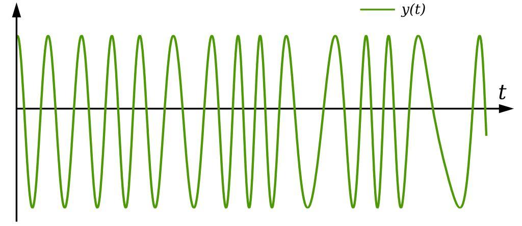
| Keywords: FM Modulated Signal.svg A graph showing an FM modulated signal The modulating message and carrier signals are given respectively as <math>x_m t 0 65 \left 0 2 \sin t + 0 5 \cos 2 t + \cos 4 5 t \right</math> <math>x_c t A \cos 2 \pi f_c \ </math> where <math>A 2\ </math> <math>f_c 3\ </math> The modulated signal is then given by <math>y t A \cos \left 2 \pi \int_ 0 t \left f_c + x_m \tau f_\Delta \right \ d \tau \right </math> where the frequency deviation is given by <math>f_\Delta 0 15\ </math> self-made in Inkscape 2008-02-16 Inductiveload Modulating and Carrier Signals Frequency modulation | ||||